




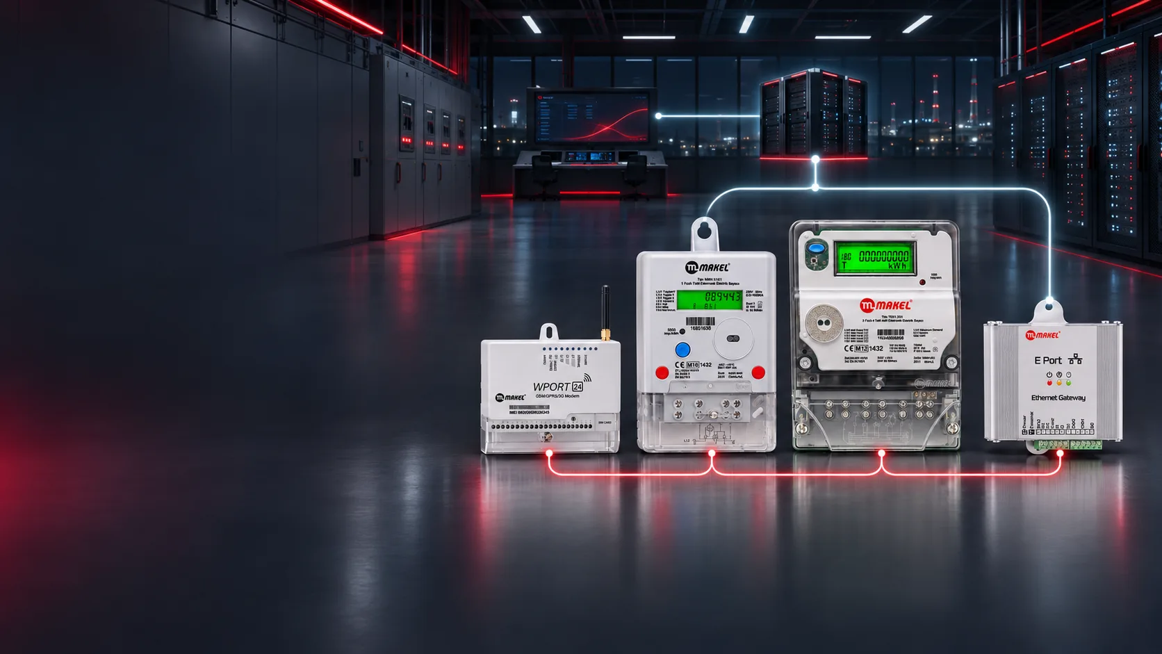
A practical architecture for connecting 500 electricity meters to a central IP network and management computer through 42 modems/gateways, including RS485 segmentation, capacity calculation, security, commissioning and operations.
In large residential developments, mixed-use buildings, industrial facilities, campuses and shopping centres, reading hundreds of electricity meters manually takes time and increases the risk of errors, delays and inconsistent records. A central meter automation system collects measurement data from the field over a controlled communication network and makes it available for reporting and analysis through authorised management software.
This article explains a scalable example for 500 meters in which up to 12 meters are assigned to each modem or gateway. The figure of 12 meters per gateway is a project design criterion, selected to keep cabling, fault domains, commissioning and maintenance manageable. It must not be interpreted as the manufacturer’s maximum device capacity.
How Many Gateways Are Needed for 500 Meters?
If each communication group contains no more than 12 meters:
- 41 full groups × 12 meters = 492 meters
- Final group = 8 meters
- Total = 500 meters
- Required active modems/gateways = 42
Therefore, 41 gateways serve 12 meters each and the final gateway serves eight. One or two spare units may be held according to the operator’s maintenance policy, but spares are not included in the total of 42 active devices.
Technical note: Makel’s E Port documentation states that its RS485 port supports up to 255 connections. Actual project design must still consider bus length, cable type, topology, baud rate, electromagnetic conditions, maintenance strategy and the impact of a segment failure. The 12-meter grouping in this example deliberately creates smaller and more manageable field segments rather than using the theoretical maximum.
Example Meter Automation Architecture
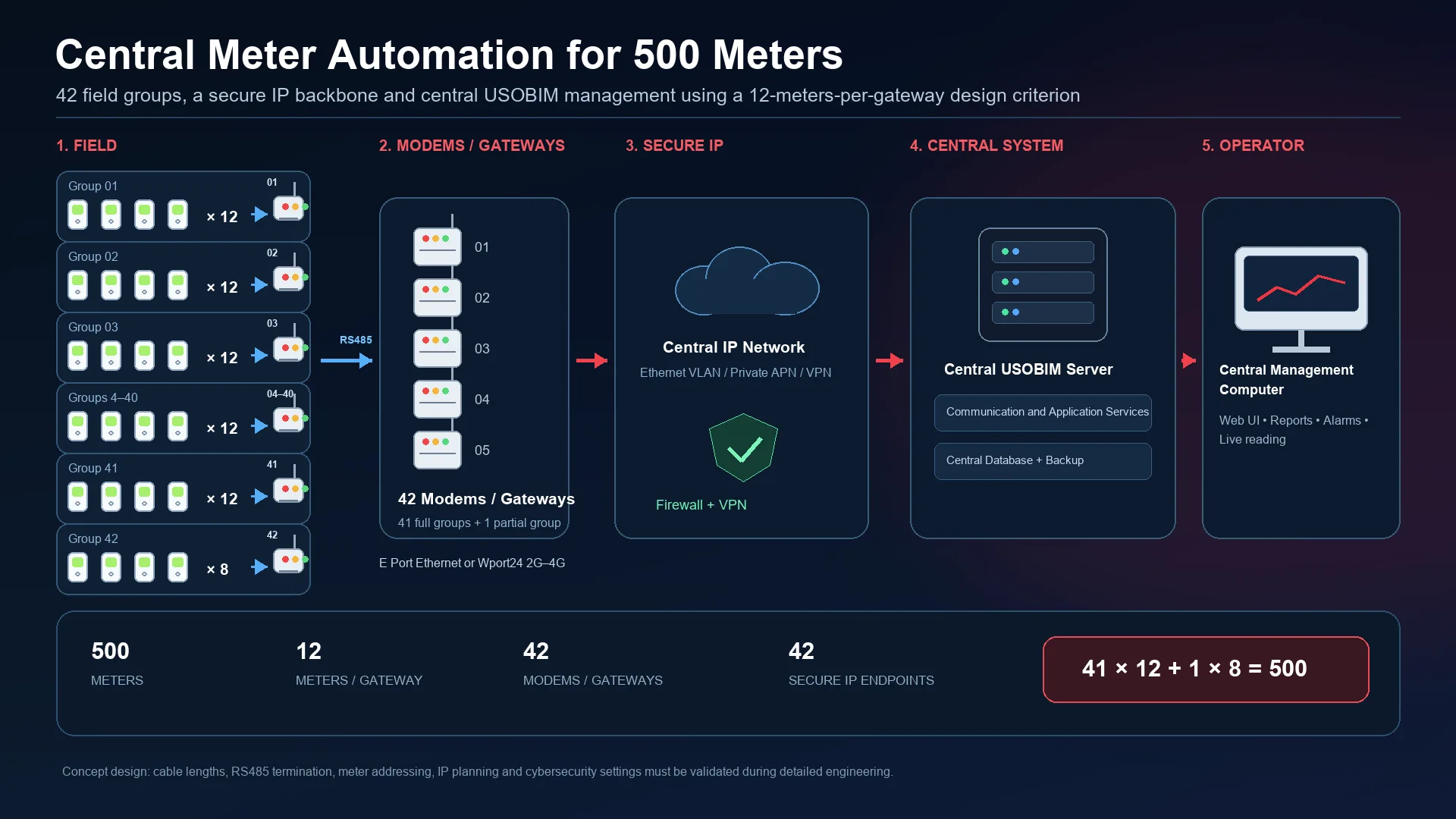
Five hundred meters connect to the secure central IP platform through 41 groups of 12 meters and one group of eight, using 42 modems or gateways in total.
The proposed data path consists of the following layers:
- Measurement layer — 500 meters: Electricity meters produce consumption, active/reactive energy, demand and other model-dependent data.
- Field communication — 42 RS485 groups: Up to 12 meters communicate on each properly designed RS485 bus. The final group contains eight meters.
- Modem/gateway layer — 42 devices: Each field group reaches the IP network through a modem or Ethernet gateway. Depending on the site infrastructure, the design may use an Ethernet/TCP-IP gateway such as E Port or a mobile communication device such as Wport24.
- Central IP network: Gateways connect to managed switches, a dedicated metering VLAN and the firewall/VPN layer.
- Central application and data layer: USOBIM or another approved central meter-reading platform collects, stores, reports and analyses authorised meter data.
- Management computer: Operators connect from an authorised workstation to monitor meters, communication status, consumption curves and reports.
Exact Flow for the Architecture Diagram
500 Electricity Meters → 42 RS485 Groups → 42 Modems/Gateways → Managed Ethernet Switches → Metering VLAN + Firewall/VPN → Central IP Network → USOBIM/Application Server + Database → Central Management Computer
The diagram should also show:
41 groups × 12 meters = 492 meters
1 group × 8 meters = 8 meters
Total = 500 meters / 42 modems-gateways
Designing the RS485 Field Layer
For stable RS485 communication, meters should be arranged in a bus or daisy-chain topology in accordance with the device and project documentation rather than an uncontrolled star topology. Correct polarity, suitable termination, screened twisted-pair cable, appropriate earthing and systematic addressing are essential.
The commissioning record for every group should include:
- Modem/gateway identifier and IP address
- Unique addresses of all connected meters
- Building, floor, panel and location information
- RS485 segment number, cable route and termination points
- Baud rate and protocol settings
- Test, commissioning and latest maintenance date
Twelve-meter segments reduce the scope of troubleshooting. A fault in one group does not stop the remaining 41 groups; the maintenance team can focus on the relevant gateway and its connected meters.
Carrying Data from the Gateways to the Central IP System
Where an Ethernet infrastructure is available, gateways may connect to the local IP network through RJ-45. Mobile-enabled modems may be used at remote points or where structured cabling is not practical. In both cases, the objective is to deliver meter data only to the authorised central application.
The IP plan should document the address, device name, block/group mapping and port information for each gateway. Metering traffic should be separated from office and guest networks. Only required communication paths should be permitted, and remote access should use a VPN or another channel approved by the organisation’s security policy.
What Can Be Monitored at the Central Workstation?
Depending on the selected meter and software functions, the platform may support:
- Scheduled or on-demand meter reading
- Consumption reports and period comparisons
- Active and reactive energy monitoring
- Demand and load-profile analysis
- Detection of offline meters or gateways
- Investigation of abnormal consumption
- Data to support billing and sub-meter reconciliation
- Remote status checks before a field visit
Makel’s official E Port documentation describes TCP/IP, Ethernet, RS232/RS485 and USOBIM compatibility. USOBIM can provide the remote-reading and central reporting layer. Final functions must be confirmed against the exact meter model, gateway, software licence and communication infrastructure selected for the project.
Implementation Steps
1. Survey and point schedule
Record the building, floor, panel and purpose of every meter. Verify meter types, communication ports and the existing cable infrastructure.
2. Create 42 communication groups
Use physical proximity and panel layout to form 41 groups of 12 meters and one group of eight. Mark every group on single-line diagrams and floor plans.
3. Design the RS485 layer
Define the cable, route, segment length, addressing, termination and field-earthing method.
4. Prepare the IP and cybersecurity plan
Assign addresses and device names for 42 gateways, then define the VLAN, firewall rules, VPN access and user roles.
5. Configure the central software and database
Prepare the application server, database, user roles, report templates, retention policy, backups and time synchronisation.
6. Commission in stages
Test one pilot group first, then commission the remaining groups by block or panel. Compare the local meter display with the value received by the central system.
7. Run acceptance tests
Verify the visibility of all 500 meters, the online status of all 42 gateways, report accuracy, alarm scenarios and access rights. Test communication loss and recovery as separate scenarios.
8. Handover and operator training
Deliver the IP list, meter address register, RS485 group plan, operating guide, backup procedure and test records to the facilities team.
Security and Continuity Measures
- Use a dedicated VLAN or network segment for meter automation.
- Permit gateway access only from required IP addresses and ports.
- Protect remote access with VPN and role-based permissions.
- Replace default passwords and log user actions.
- Support the server, network equipment and critical gateways with UPS power.
- Back up the database and perform recovery tests regularly.
- Generate alarms for offline devices, delayed data and clock drift.
- Keep the IP plan, device inventory and as-built drawings up to date.
Why Use Groups of 12 Meters?
Even when a gateway has a higher theoretical capacity, smaller field groups can provide:
- Shorter, clearer cable routes
- A smaller fault domain
- Faster testing and commissioning
- Clear responsibility by block, floor or panel
- Easier device and address tracking during maintenance
- Controlled capacity planning for future extensions
The final group size should be established through engineering analysis of site layout, distances, electromagnetic conditions, budget and operational objectives.
End-to-End Meter Automation with Aret Engineering
Aret Engineering brings meter selection, site survey, RS485 segmentation, modem/gateway placement, the central IP network, USOBIM integration, commissioning, reporting and operator training together under one coordinated project discipline.
For a 500-meter development, the goal is not simply to read data remotely. The real objective is to transform 500 measurement points into a secure, traceable and maintainable energy-management infrastructure.
Share the number and distribution of meters and your existing communication infrastructure with us. We will develop the field grouping, gateway and central-system architecture for your project.
Frequently Asked Questions
Why are 42 gateways required for 500 meters?
This example limits each gateway to 12 meters. Forty-one gateways collect 492 meters, while the final gateway collects eight, giving a total of 500 meters through 42 active gateways.
Is 12 meters a product limitation?
No. Twelve meters per gateway is a project design criterion used to keep field segments manageable. The manufacturer’s documented capacity, line conditions and project requirements must be evaluated separately.
How are the meters connected to a gateway?
Compatible meters typically communicate over an RS485 field bus. Addressing, cable type, topology, termination and communication parameters must follow the project and product documentation.
How do gateways reach the central platform?
The design may use Ethernet/TCP-IP or mobile data, depending on the site. Traffic is routed through the firewall/VPN layer to the central meter-reading application.
Must the central workstation be exposed to the internet?
No. The system may operate inside the corporate network or provide controlled access from remote locations through an approved security architecture.
Does one communication failure stop the entire system?
With 42 separate field groups, a fault in one gateway or RS485 segment does not directly stop the other groups. Alarm behaviour and local data buffering must still be verified for the exact hardware and software used.
Technical Sources and Related Solutions
- Makel Electronic Electricity Meters
- Makel Wport24 and E Port Communication Solutions
- Makel USOBIM Meter Automation
- Aret Engineering Meters and Meter Automation Solution
ARET MUHENDİSLİK Team
← All Posts